I don’t typically work on these radios because everything is surface mount and trying to get to a lot of the components means a complete disassembly of the chassis, but last summer I worked on a 252 for a guy who who’s display lights were completely out. I’ve seen a few radios for sale on Ebay and other sites with one of the two bulbs out but never both. So I decided to give it a go and see what happens.
I looked over the schematic and found that they used a basic Series Regulator circuit to power both bulbs. Easy enough, right? Well this circuit is buried beneath the back of the front panel so the front panel has to be removed to replace any of the components and one of the two wheat bulbs is hidden in a pretty tight space. Needless to say, I still took it all apart to do the testing.
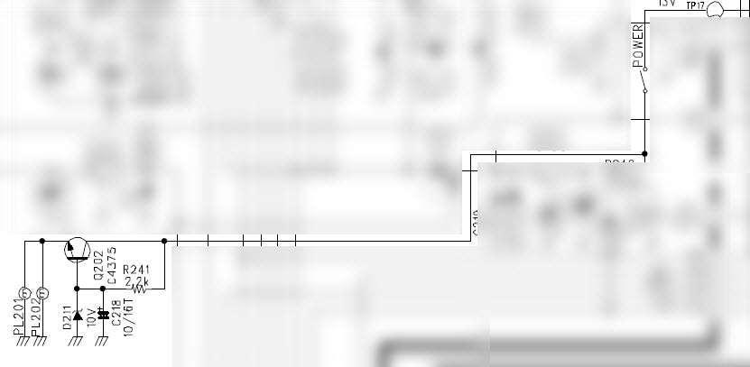
Above, is a snippit of the bulb circuit. PL201 and PL202 are both 10V 60ma pilot bulbs that have yellow caps on them. I checked the voltage at the Collector of Q202 and I had the 13V that the schematic suggests so that was good. Then, because both of the bulbs were out, I decided to check the output voltage at the Emitter of Q202 where my readings indicated a voltage of about 1.5VDC. That was bad… Since this is a 10V regulator circuit, I should have had 10V.
At this point, you can opt to dig even deeper to find which component or components failed but I wasn’t about to go that route just for a lighting circuit where the bulbs are already 20 years old and could fail any time anyway.
So what I did, is I ran a new wire to the 13V switched source and ran it to a 560 Ohm dropping resistor to a brand new yellow LED pointed directly at the reflective material used by the light bulbs to spread out the light evenly.
This was just sort of an off the cuff repair to get the display to light up and may or may not have been the best way to do it but here is the result.
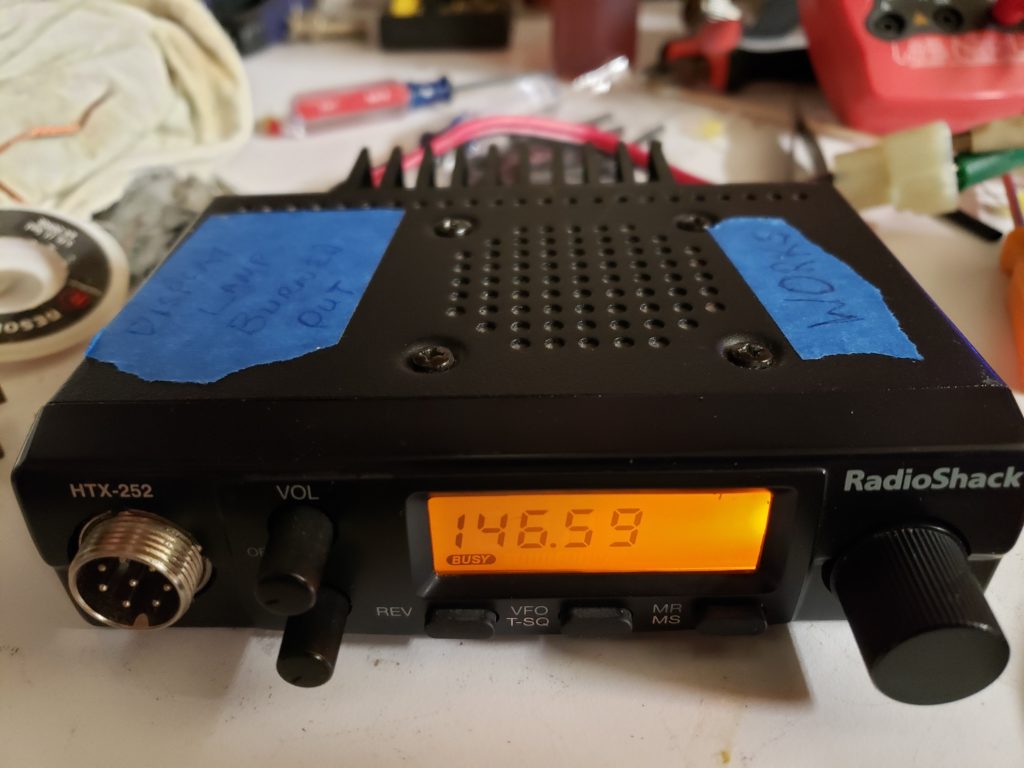
The part of the display on the right where the light looks brighter was amplified by my phone when I took the picture. It didn’t really look that bright in person.
Unfortunately I was too immersed in this repair to remember to take pics as I went along but it was pretty straight forward.
- Find a switched 13V location and solder a thin wire to it.
- Solder the dropping resistor to that wire.
- Solder the longer leg of the yellow LED to the dropping resistor.
- Solder the shorter leg of the LED to ground.
There is only enough room for an LED on the right side of the display looking at it from the front. You may or may not have to remove the original bulb that is already in that space. I opted to remove it.
You’ll also have to point the LED in towards the display so that the reflective plastic can do it’s job. It takes a little playing with to get it where you want it. Once you find the right position, you can hot glue it in place.
If you’re of the purist type, you can also just replace the components causing the outage. It looks like you’ll need SMT tools and a whole lot of patience! Good Luck!
73 for now!
KU4BY